UNR Renovators
Civil Engineering Capstone Team — University of Nevada, Reno
Designing resilient infrastructure for Nevada communities
Learn MoreCivil Engineering Capstone Team — University of Nevada, Reno
Designing resilient infrastructure for Nevada communities
Learn MoreUNR Renovators is a civil engineering capstone team from the University of Nevada, Reno. Our team brings together expertise in structural design, hydrology, transportation engineering, geotechnical analysis, and construction management to deliver practical, community-focused infrastructure solutions.
As part of the CEE 426/427 Capstone Design sequence, we work on real-world engineering challenges under the guidance of professional mentors and faculty advisors. Our approach combines rigorous technical analysis with a commitment to safety, sustainability, and constructability.
Four civil engineering students bringing diverse skills and experience to infrastructure design.

Structural Design Lead
Project Management & Transportation
Hydrology & Water Resources

Construction & Cost Estimation
Rock Boulevard in Sparks, Nevada is a critical north–south transportation corridor connecting industrial, commercial, and residential areas near the Interstate 80 interchange. The segment between Hymer Avenue and Victorian Avenue passes beneath a Union Pacific Railroad bridge where the roadway profile creates a low point that is highly susceptible to stormwater ponding and roadway flooding.
During heavy rain events, this underpass frequently experiences closures, unsafe driving conditions, and traffic congestion. Two documented flooding events in July and August 2025 resulted in complete closure of the underpass, requiring emergency response and traffic rerouting.
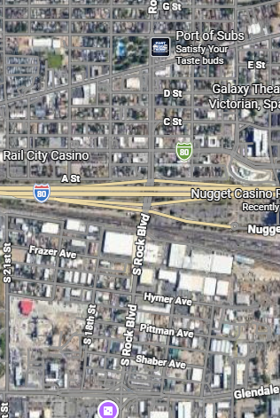
Project vicinity — Rock Boulevard near the I-80 interchange, Sparks, NV
Three design alternatives were analyzed. Alternative 1: Drainage and Road Reconstruction was selected as the preferred solution based on a weighted decision matrix evaluating flood mitigation, traffic safety, cost, technical feasibility, environmental impact, and service life.
~$1.65M
Weighted Score: 4.5 / 5
~$9.3M
Weighted Score: 3.6 / 5
~$4.8M
Weighted Score: 4.03 / 5
Stormwater runoff evaluation, drainage system capacity analysis, precast pump station selection, slotted drain design, and green infrastructure sizing using NOAA Atlas 14 and Rational Method.
20-ft cast-in-place reinforced concrete cantilever retaining wall replacing the existing angled wall, enabling roadway widening and improved drainage control.
Roadway regrading, WB-67 turning analysis, lane configuration improvements, green infrastructure integration, and traffic signal modernization.
Subsurface soil analysis, pavement section design, foundation requirements, and evaluation of alluvial deposits for construction suitability.
| Wall Type | Cast-in-place cantilever |
| Wall Height | 20 ft |
| Concrete Strength (f'c) | 4,000 psi |
| Reinforcing Steel (fy) | 60 ksi |
| Soil Unit Weight | 120 pcf |
| Bearing Pressure | 3,000 psf |
| Sliding FS | ≥ 1.5 |
| Overturning FS | ≥ 2.0 |
ACI 318 • NDOT Structural Specs • AASHTO LRFD
| Design Storm (Primary) | 25-Year Event |
| Rainfall Intensity (25-yr) | 2.86 in/hr |
| Peak Runoff (Q25) | 42.77 cfs |
| Runoff Coefficient | 0.91 |
| Method | Rational Method |
| Conveyance | Manning's Equation |
NDOT Drainage Manual • FHWA HEC-22 • NOAA Atlas 14
| Design Vehicle | WB-67 (AASHTO) |
| Posted Speed | 30 mph |
| Lane Width | 12 ft |
| Stopping Sight Distance | ≥ 200 ft |
| Lateral Clearance | 1.75 ft each side |
AASHTO Green Book • MUTCD • NDOT Standards
Rankine Active Earth Pressure Theory for lateral loading analysis. Cantilever retaining wall design including stability checks for sliding, overturning, and bearing capacity. Reinforced concrete design per ACI 318 with shear key and drainage provisions.
Rational Method for peak runoff estimation. Manning's Equation for storm drain capacity. Precast pump station selection and performance evaluation. Slotted drain sizing for roadway runoff interception. Water Quality Volume (WQv) compliance verification. Multi-event storm analysis (25, 50, and 100-year).
Stopping Sight Distance verification per AASHTO Green Book. WB-67 design vehicle turning analysis. Lane configuration and intersection geometry optimization. Traffic signal modernization. Green infrastructure integration along widened roadway.
Soil classification using USCS and AASHTO systems. Web Soil Survey data interpretation. Foundation design for retaining wall systems. Evaluation of alluvial deposits for construction suitability and groundwater considerations.
Stormwater quality treatment and erosion control. Green infrastructure design using permeable landscaping with native shrubs and rock for infiltration and runoff reduction. Best Management Practices for construction. Sustainability evaluation across economic, social, and environmental metrics.
Multi-alternative feasibility comparison using weighted decision matrix. Engineer's cost estimation with itemized quantities. Project scheduling with Gantt chart milestones for Innovation Day presentation.
Key specifications from the 7-sheet engineering drawing set (C000–C401) for the Rock Boulevard rehabilitation.
| Wall Types | Type 1A, Type 1B/1C, Type 2 |
| Reinforcement | No. 5 @ 18″ top & bottom |
| Clear Cover | 2″ typical |
| Batter | 1:12 |
| Min. Cover | 4″ min at base |
| Key Bar & Shear Key | No. 5 equally spaced |
| P.C.C. Strength | 4,000 psi min (28 day) |
| Aggregate Base | 4″ min, 95% relative compaction |
| Sidewalk Joint Spacing | Every 5 ft — weakened plane joints |
| Curb & Gutter Joints | Every 10 ft, back/top/face of curb |
| Standard Details | City of Sparks S-103, S-109 |
| Existing Pavement | 4″ AC on 8″ aggregate base |
| Asphalt Spec | PG64-28NV, 2″–4″ lifts |
| Storm Drain Pipe | Class III RCP, watertight joints |
| Proposed Width | 32 ft roadway + 12 ft lane + 6 ft sidewalk |
| Key Improvements | New pump station, retaining wall, slotted drains, rock & shrubbery |
The Rock Boulevard Rehabilitation Project directly addresses the safety, mobility, and economic needs of the Sparks community. By resolving recurring flooding and improving roadway infrastructure, this project delivers meaningful benefits to the people and businesses that depend on this corridor every day.
Documented in July and August 2025, each requiring emergency response and full road closure.
Crash history highlights the need for improved geometry, turning radii, and signage.
Existing pump capacity (~10–12 cfs) vs. required capacity (~108 cfs) during storm events.
Engineering drawings, renderings, and design schematics illustrating the proposed Rock Boulevard improvements.
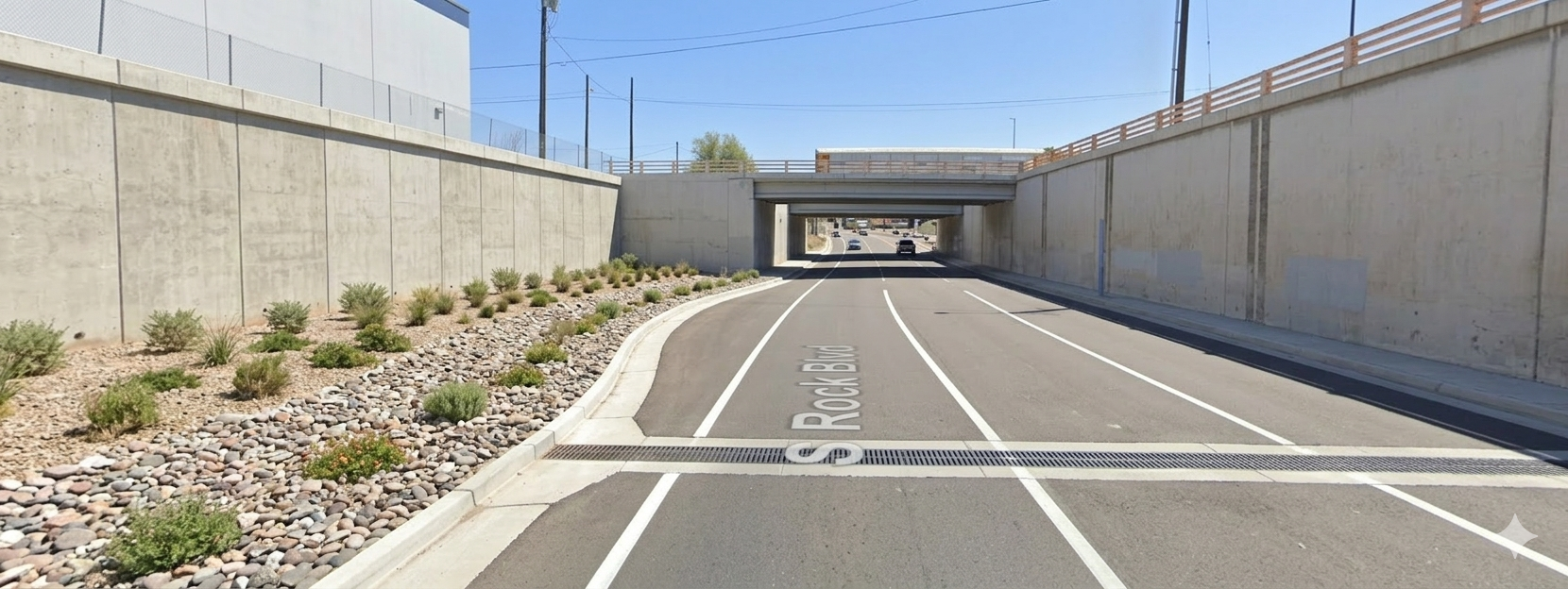
Project Rendering — Completed Rock Boulevard looking south toward UPRR underpass
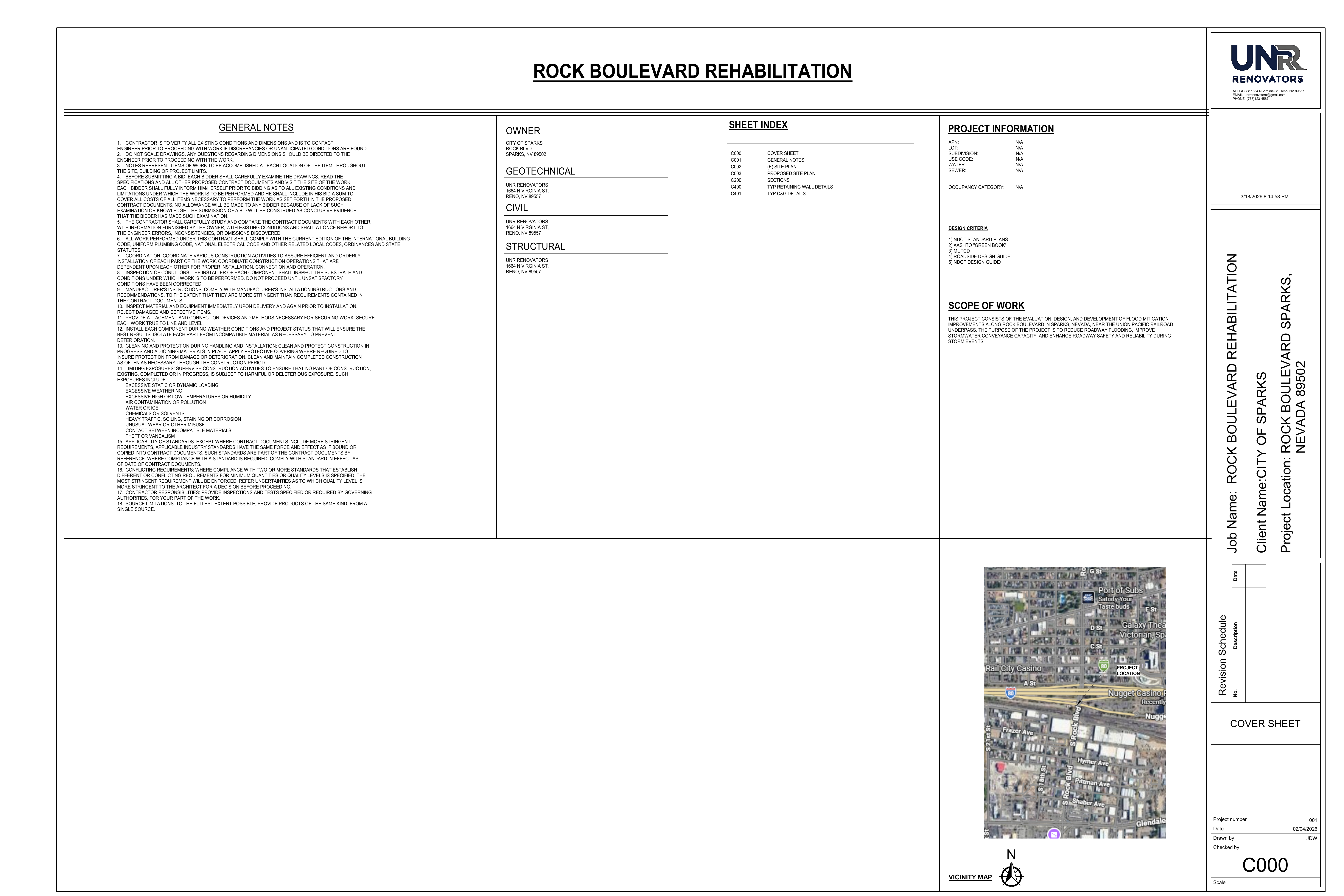
C000 — Cover Sheet & Vicinity Map
Project Vicinity Map
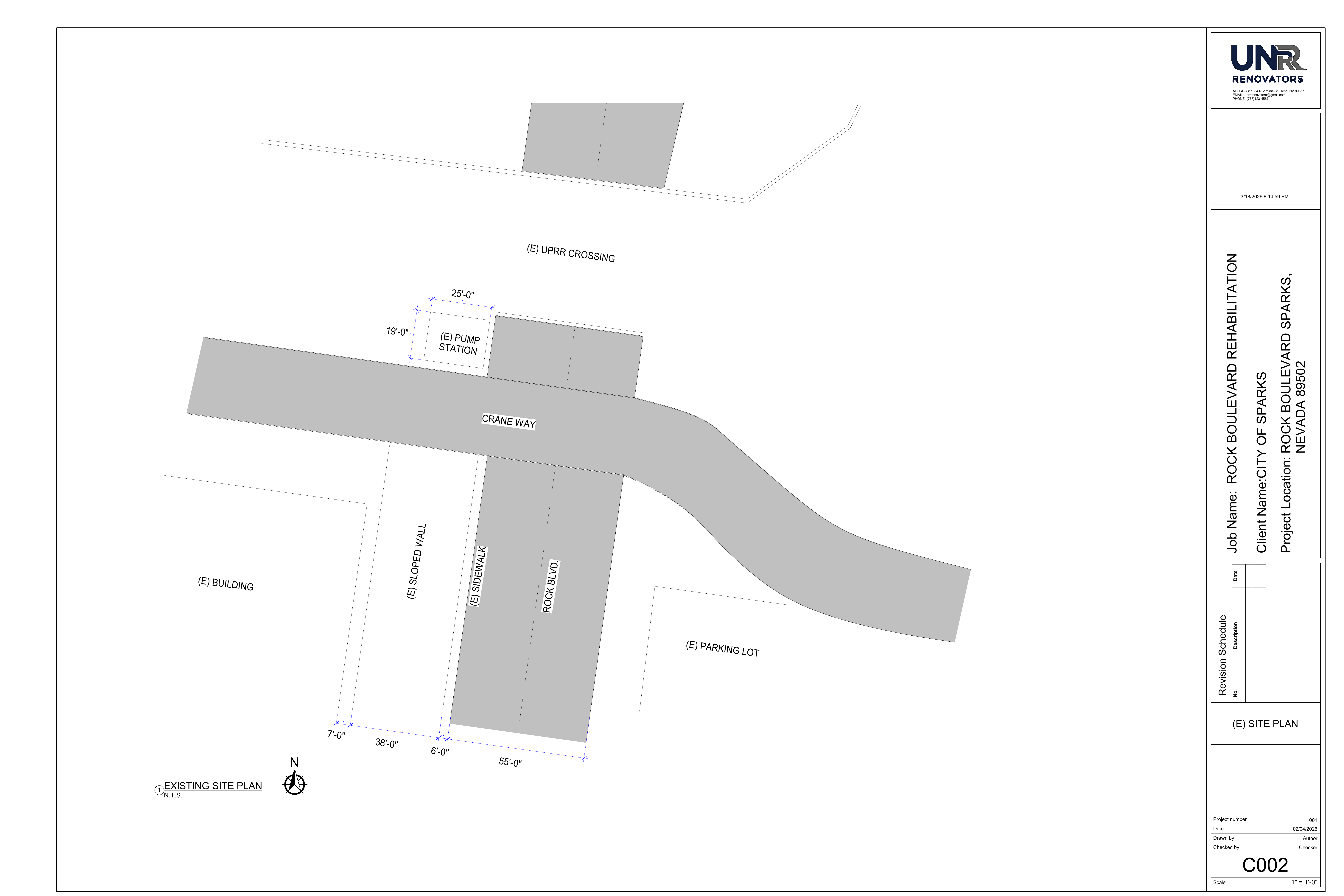
C002 — Existing Site Plan
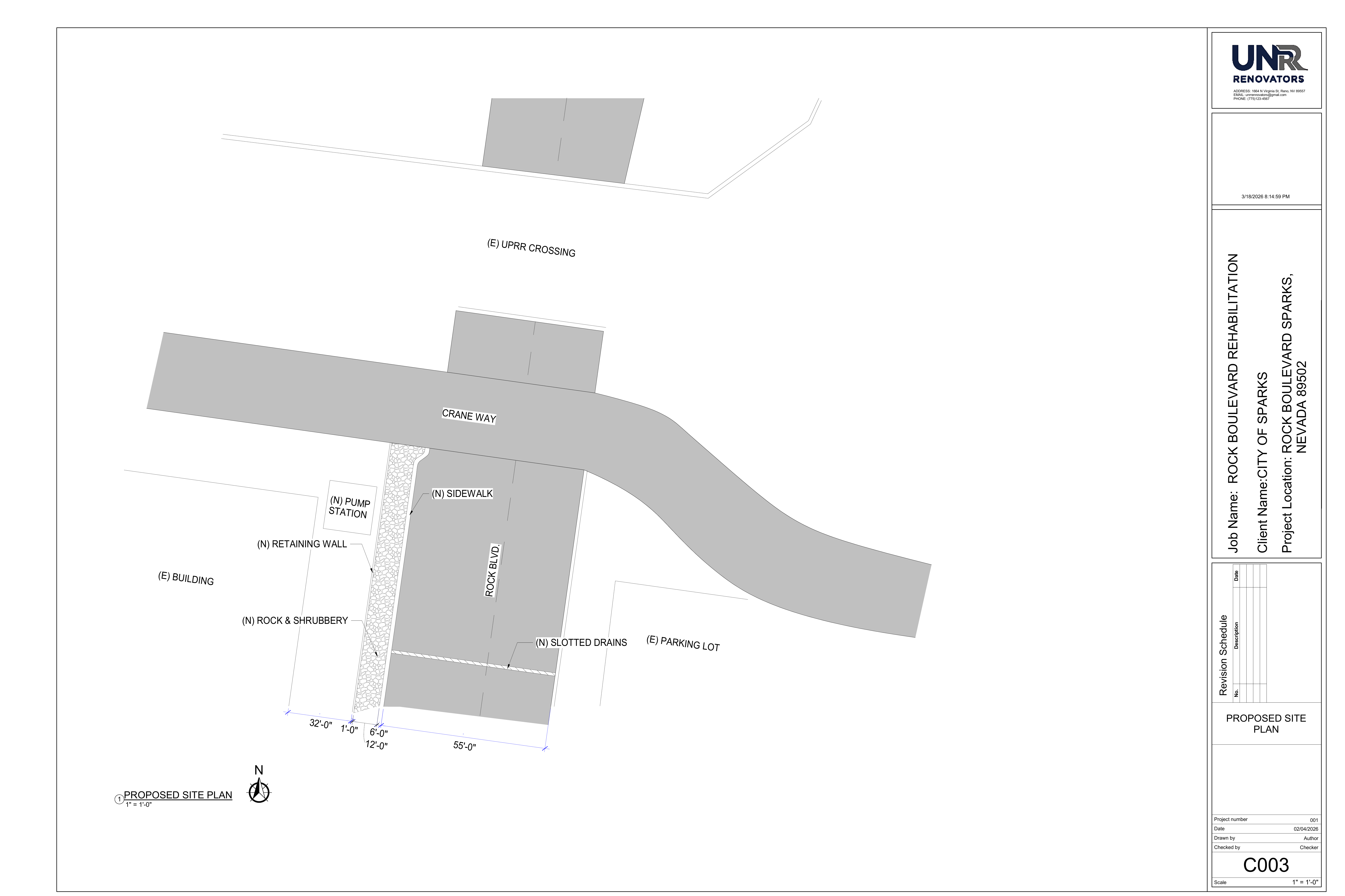
C003 — Proposed Site Plan
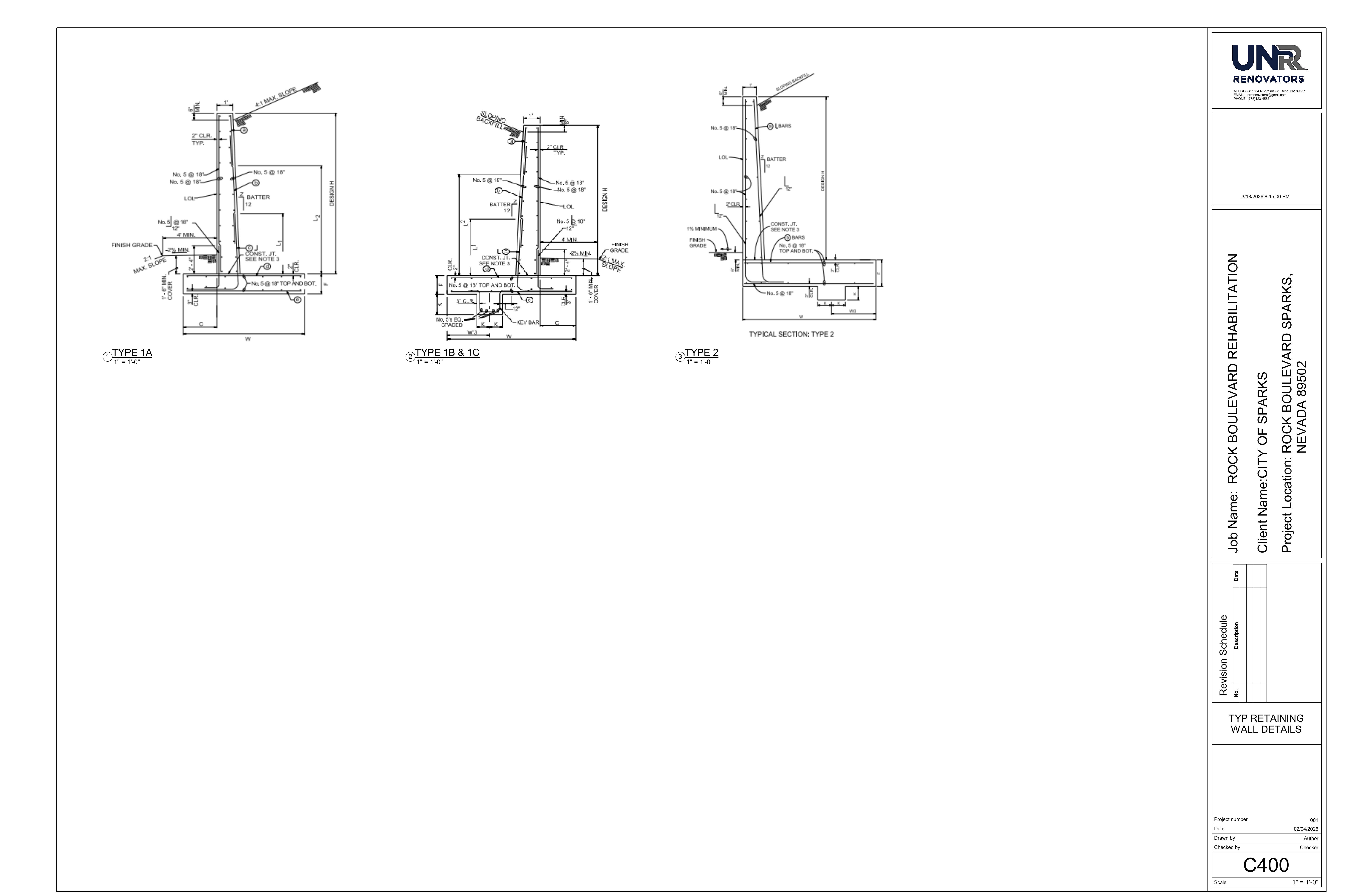
C400 — Retaining Wall Details (Type 1A, 1B/1C, Type 2)
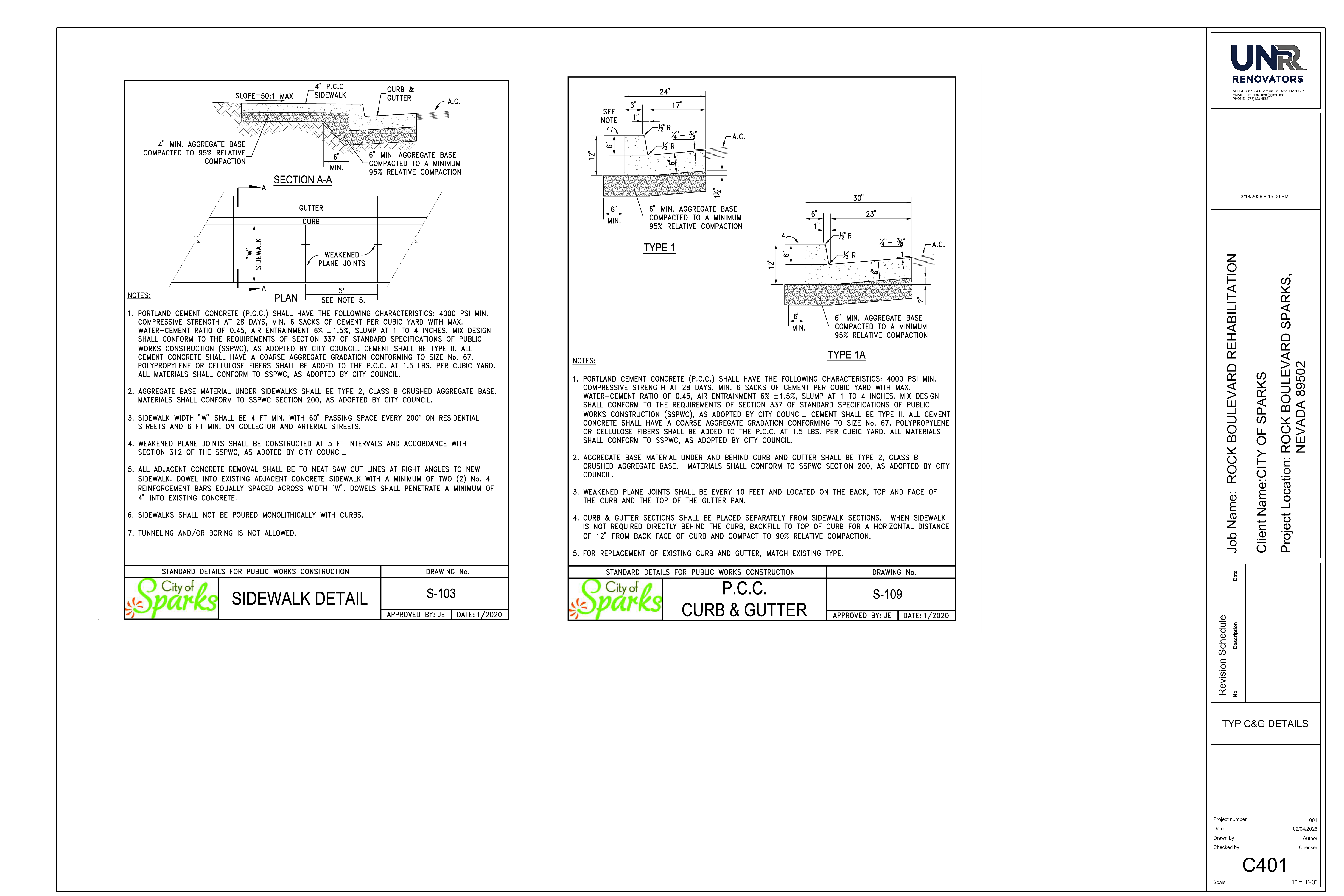
C401 — Curb & Gutter Details (S-103, S-109)
Prepared for the University of Nevada, Reno College of Engineering.